
Line Stop Project Case Study:
Liquid Propane Facility Seasonal Cooling Project
PROBLEM
A Liquid Propane Export Facility in Northern Western Canada was unable to store and complete offload transfers during the summer months when temperatures are warm, due to limited cooling capabilities on the system, and an inability to de-pressure as storage systems would boil off with to much expansion and product would need to be flared off.
SOLUTION
This facility contacted Red Flame Industries (Taurus Industrial) to determine if an in-service solution could be found to successfully keep the system on pressured while installing new mainline valve and tie points to route new HP and LP system coolers. By being able to run chillers during the summer months, the facility could project an additional 3-4 shipments overseas and gain a large amount of missed revenue (typically lost due to external temperatures).
To keep the system in-service and pressured, size on size hot tap fittings were designed to meet provincial certifications and installed using in-service welding techniques. The branches were designed to accommodate High Pressure Pivoting Head Line Stops, as well as by-pass piping. By design, these hot tap connections were also to be used as the main inlet and outlet lines from the chillers following the linestop work, and avoiding the need for additional hot tap branches on the line.
Pivoting Head Line stops provided upstream and downstream isolation with a reduced size by-pass line off the line stop launchers. The isolation points were then drained using 2” (TOR)Thread-o-ring fittings to allow for completion plugs to be installed after draining. Once the piping section was drained, the mainline was cold cut on two locations, Weld neck flanges then installed, pressure tested using Isolation-DBB Test Plugs, and X-Rayed before insertion of new mainline isolation point TOV Butterfly valves were installed, torqued and equalized with the by-pass piping. Once equalized, linestops and by-passes were removed, and chiller piping was connected and brought into operation.
DETAILED OVERVIEW OF SCOPE
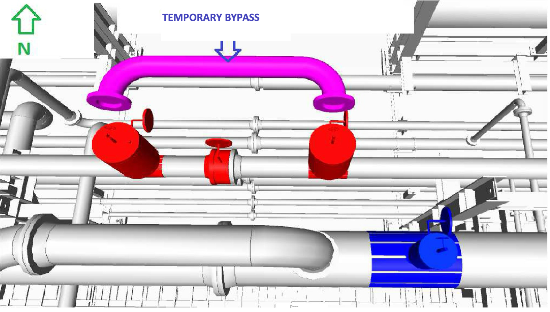
Fig. 1–10” Line Stop Locations
Perform Hot Tap on the 10" Dry LPG header, which utilizes in-service install of a 10” x 10” (Low Temp.) Split Tee with flange and 10" DIB-1 ball valve at both A and B Tie Point locations. Ensure that the dimensions of the temporary bypass spool match the distance between TP-01A and TP-01B before welding the split tee.
2. Following hot tap drill out, perform Installation of line stop launchers with 8" temporary bypass spool.
3. Insert line stops and confirm adequate working isolation (blocking of the flow) on each side of the location ofthe new 10" TOV Butterfly Valve to be installed.
4. De-energize/ bleed off the isolated section of the pipe where the new 10" TOV Butterfly Valve will be installed through the hot tapped 2" TOR Fitting to vent the gas.
5. Once accepted hold is in place (4-12 hours), proceed with cold cutting the pipe at the new a new flange locations and weld flanges. Ensure that the new TOV Butterfly Valve will fit precisely in between flanges with gaskets before welding the new flange proceeds.
6. During and following welds, perform Non-Destructive Testing techniques to confirm the weld is acceptable. Slide the isolation test plug ahead and perform a pressure test on the the new flange weld on either side and is tested in compliance with the test pressure.
7. Install the new 10" TOV Butterfly Valve by bolting it to the existing flange and newly installed flange. Ensure step up and torque spec are met and accepted by QC.
8. Equalize the new section to the by-pass line, and remove the line stops back into the launchers and unblocking the flow. Proceed to open the new 10" TOV Butterfly Valve, and remove launchers and 8" temporarybypass spool from each ball valve.
9. Installation of vented blind on each 10" ball valve until new chiller piping can be installed.
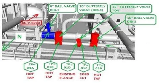
Fig. 2–Images of Final Modeling with Hot Tap Branch & New Isolation Valves.
10. Based on new systems and tie ins, perform hot taps on 24” flare line to accommodate new PSV line for system. Flare tie ins will utilize a reducing 6” x 24” ____ Weldolet/ Flange and 6" ball valve.
11. Installation of vented blind flange on the 6" DIB-1 ball valve until new PSV piping is installed and chiller system brought on-line.
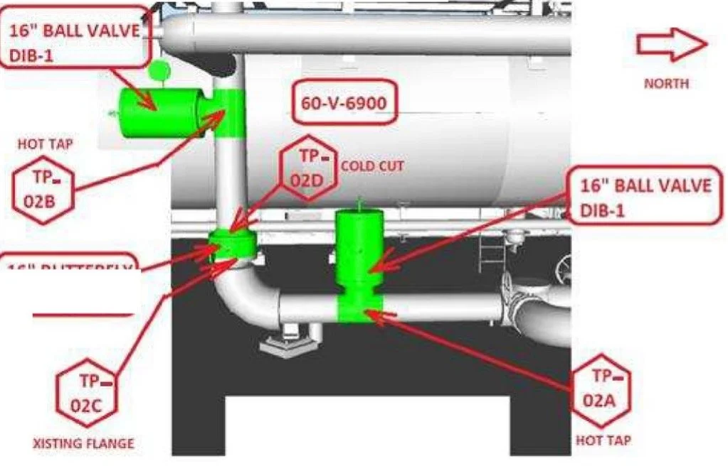
Fig. 3–Images of Final Modeling with Hot Tap Branch & New Isolation Valves.
11. Perform Hot Tap on the 16" Dry LPG header, which utilizes in-service install of a 16” x 16” (Low Temp.) Split Tee with flange and 10" DIB-1 ball valve at both A ______and B Tie Point locations. Ensure that the dimensions of temporary bypass spool match the distance. Following hot tap drill out, perform Installation of line ______stop launchers with 12" temporary bypass spool.
12. Insert line stops and confirm adequate working isolation (blocking of the flow) on each side of the location of the new 16" TOV Butterfly Valve to be installed.
13. De-energize/ bleed off the isolated section of the pipe where the new 16" TOV Butterfly Valve will be installed through the hot tapped 2" TOR Fitting to vent ___the gas.
14. Once accepted hold for safe work isolation is in place (4-12 hours), proceed with cold cutting the pipe at the new a new flange locations and weld flanges. ___Ensure that new TOV Butterfly Valve will fit precisely in between flanges with gaskets before welding the new flange proceeds.
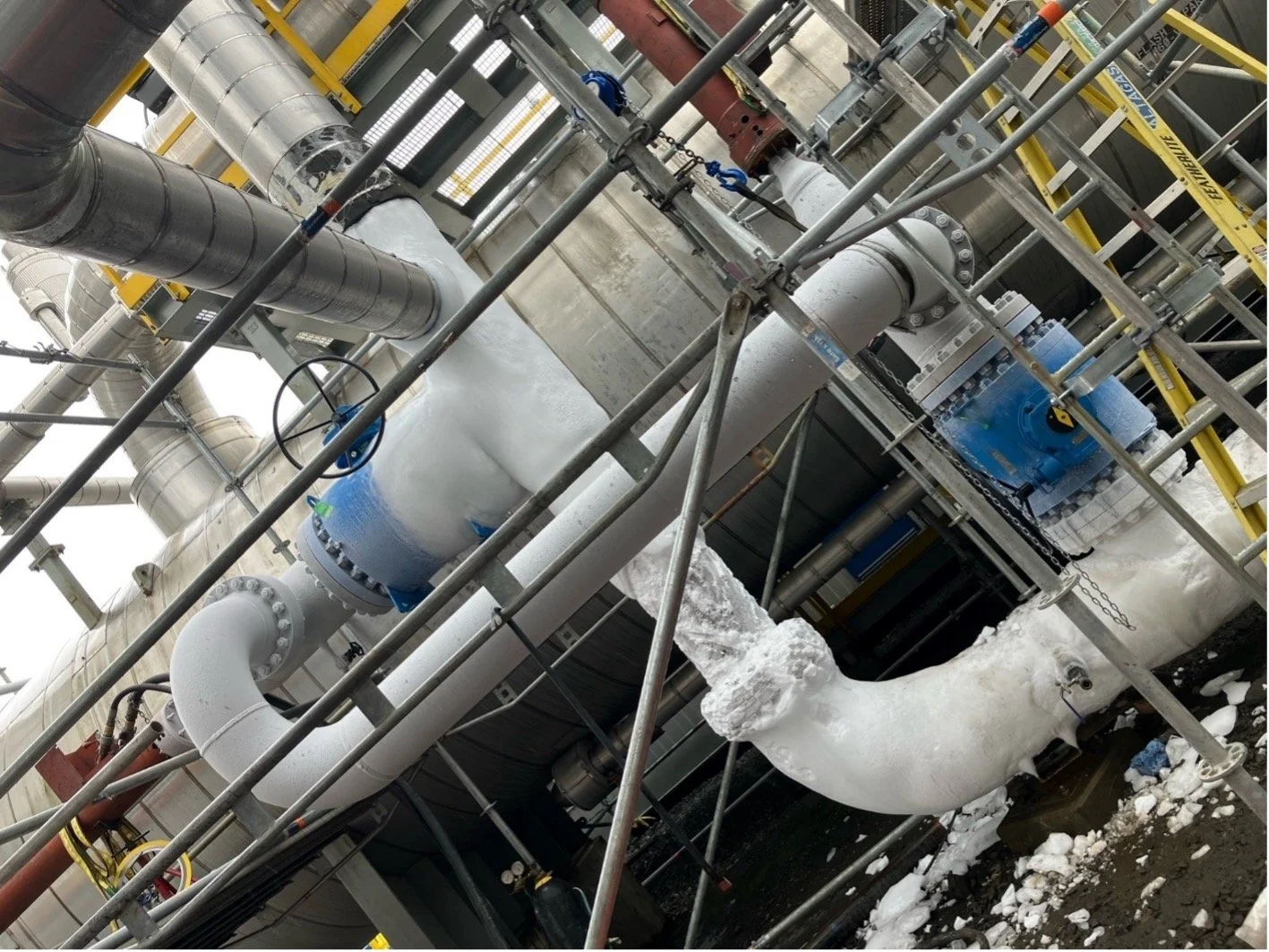
Fig. 4–Frozen System Operating with Line Stops & By-Pass in Place.
15. During and following welds, perform Non-Destructive Testing techniques to confirm the weld is acceptable. Slide the isolation test plug ahead and perform ______a pressure test on the new flange weld on either side and is tested in compliance with the test pressure.
16. Install the new 16” TOV Butterfly Valve by bolting it to the existing flange and newly installed flange. Ensure step up and torque spec are met and accepted ___by QC.
17. Equalize the new section to the by-pass line, and remove the line stops back into the launchers and unblocking the flow. Proceed to open the new 16” TOV ___Butterfly Valve and remove launchers and 12” temporary by pass spool from each ball valve.
18. Installation of vented blind flange on each 16” ball valve until new chiller piping can be installed.
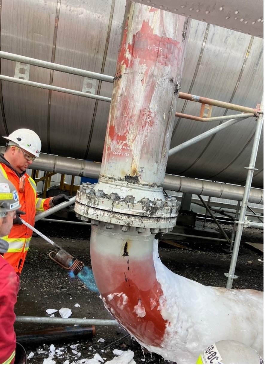
Fig. 5–Ice De-Thaw to Perform Cold Cut & New Welding of Flanges Under Pre-Heat.